Piezo Knock Detection
In this tutorial we are going to implement a door-knock detector using an Arduino and a piezoelectric sensor.
A piezoelectric sensor is an electronic component made up of special materials that generate a charge based on changes in pressure, strain or force. The ones we have available in the lab look like this:
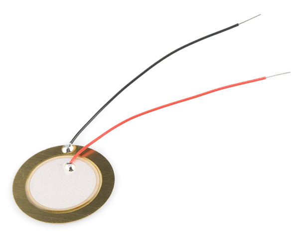
They have a positive and a negative lead, and can be connected to our Arduino and used to detect small (or big) vibrations on surfaces.
Sometimes they are used as microphones for picking up small vibrations on acoustic instruments, but for this tutorial we are going to use them to detect larger vibrations, like knocks, taps and bumps on a surface.
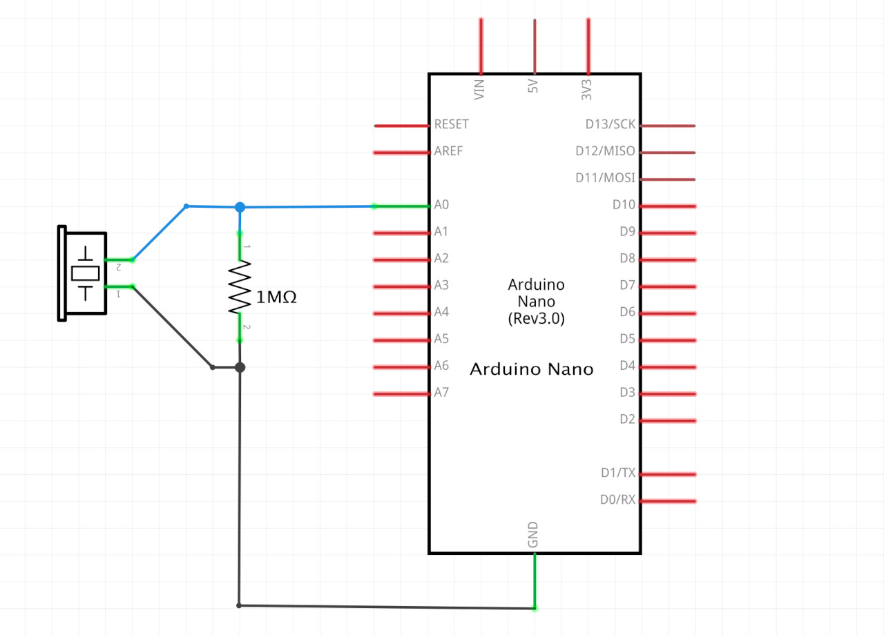
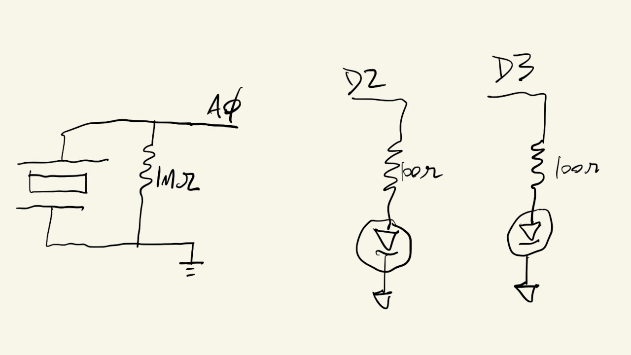
We are going to wire it up like this:
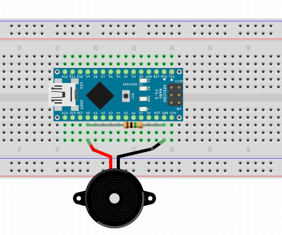
Board view:
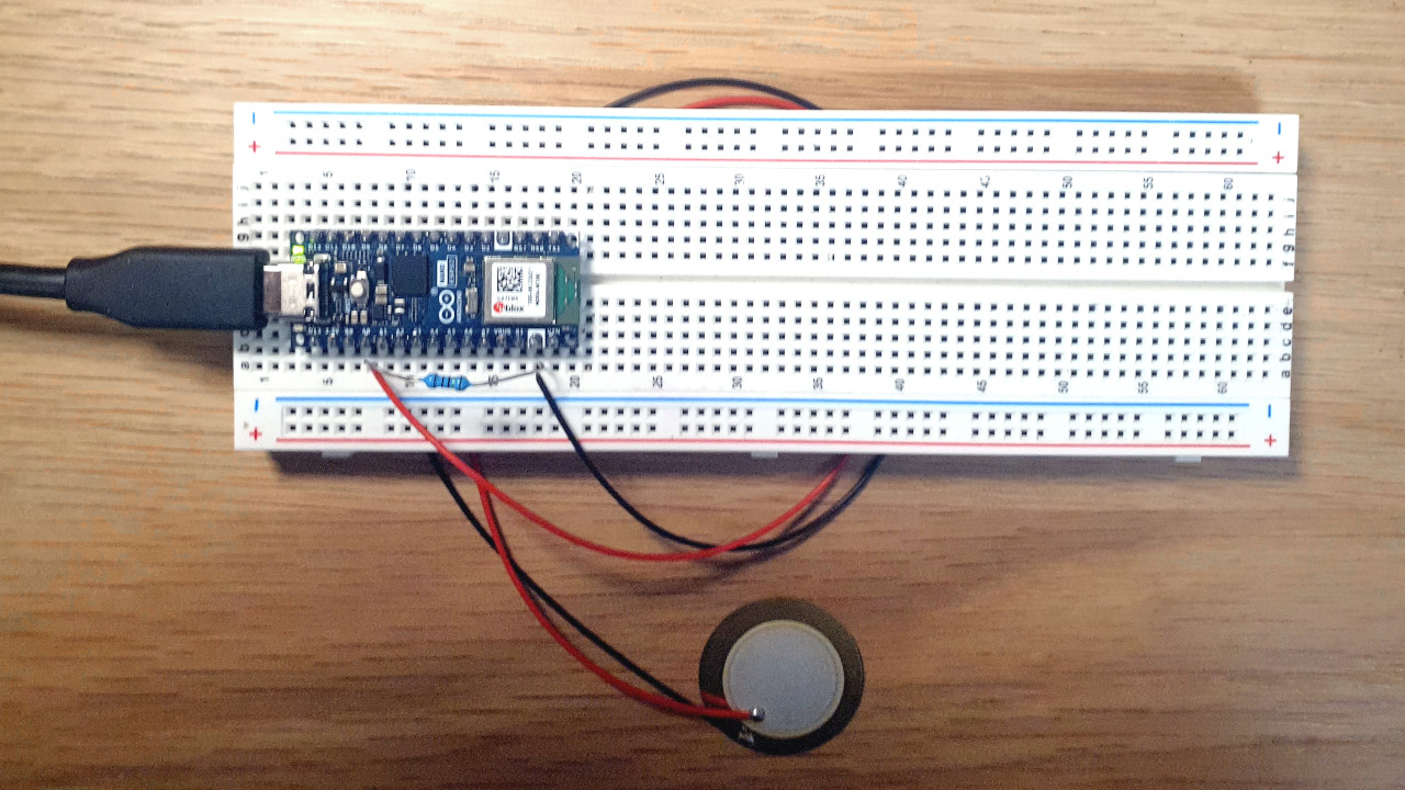
Picture:
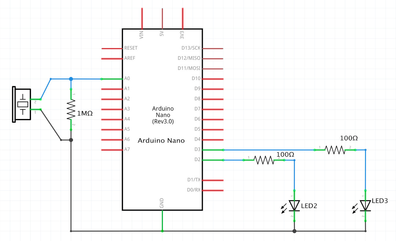
There’s a piezoelectric sensor in parallel with a 1 MΩ (Megaohm) resistor, connected to pins A0 and ground.
And the idea here is that when the piezo gets knocked, tapped or vibrated, the small current that it generates will go through the resistor, and put a voltage on pin A0, according to Ohm’s Law: \(V = I \times R\). Since the current is really tiny, we need a somewhat large resistor in order to get a voltage that is big enough to be detected by the Arduino.
Now, we can use the following code to just read the value of the voltage at pin A0 and print it to the serial monitor, as we test it with some knocks.
Serial output showing signal activity on A0:
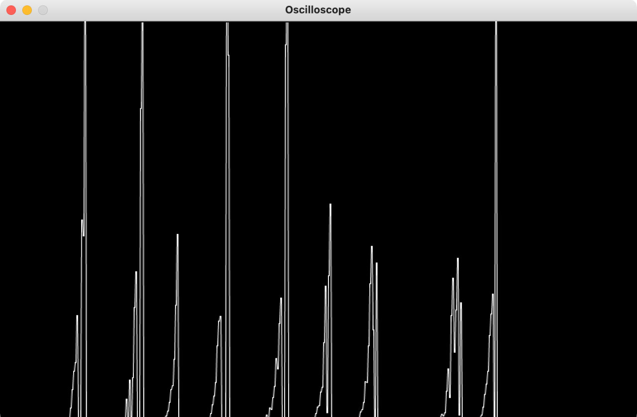
We can also graph these values using a separate program:
So the sensor seems to be working and we can detect when the surface with the piezo sensor gets hit.
Next, we want to try to count the number of knocks.
This could already be a very simple knock detector, where a door opens only if it detects exactly \(10\) knocks within \(1\) second, for example.
But first, we need to make sure we can count the number of knocks.
We can use this code as a start, which is similar to the code we used to count the number of clicks on a button:
We define a THRESHOLD value, and anytime the voltage reading at A0 is larger than this threshold, we consider that a knock.
Also, to make sure we only count once per knock, and avoid a situation where we loop so fast that we catch A0 above the threshold multiple times per loop execution, we added this check to make sure the current knock value is different from the previous knock value:
if (prevKnockValue != currentKnockValue)
This will detect transitions from \(1\) to \(0\) or from \(0\) to \(1\).
We can test our circuit by printing the value at A0, currentKnockValue and knockCount:
Hmmm….
It works. Kind of. Knocks are being double or triple counted.
If we look at the graphs from before, or at the serial monitor values, we’ll see that each knock actually produces a variety of fluctuations on the input pin. We can see in the graphs that the value at A0 goes up and down many times for each knock, and in the serial monitor we can see that sometimes we get up to \(3\) transitions from \(0\) to \(1\) per knock.
Graph of A0 over time:
Serial monitor:
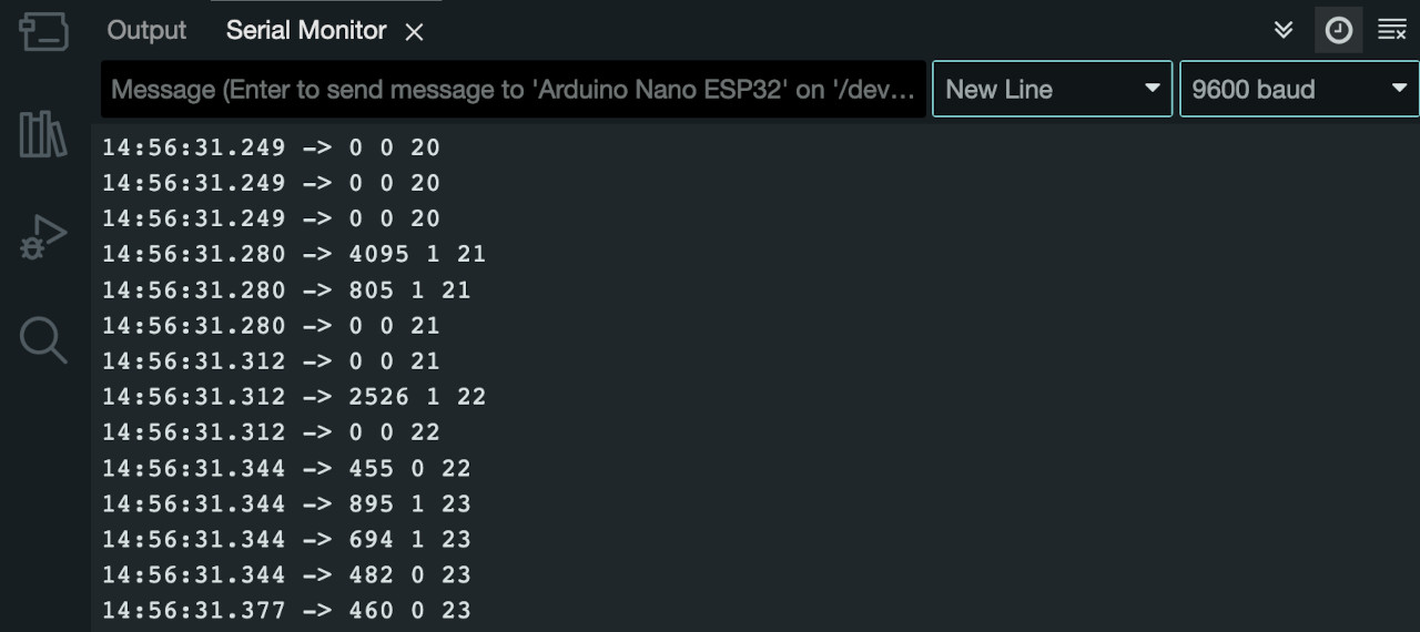
We can see that one knock makes the currentKnockValue variable transition from \(0\) to \(1\) a total of \(3\) times and our count increases from \(20\) to \(23\) with just one actual knock.
Even if we detect when a signal changes from \(0\) to \(1\), or from \(1\) to \(0\), those changes happen multiple times with each knock.
We need to debounce the signals at the input.
There are two ways of doing this.
The first way involves defining a debounce period for each detected transition. Imagine that every time we detect a transition we turn our sensor off for a few milliseconds. This will make it so we detect the first transition (from \(0\) to \(1\), or \(1\) to \(0\)), and then ignore the others for a few milliseconds.
The code can be implemented like this:
And if we test it by knocking on the board, and by inspecting the serial monitor output, we’ll see that if when the signal fluctuates up and down, creating a sequence of transitions, we only count the very first transition.
Serial monitor:
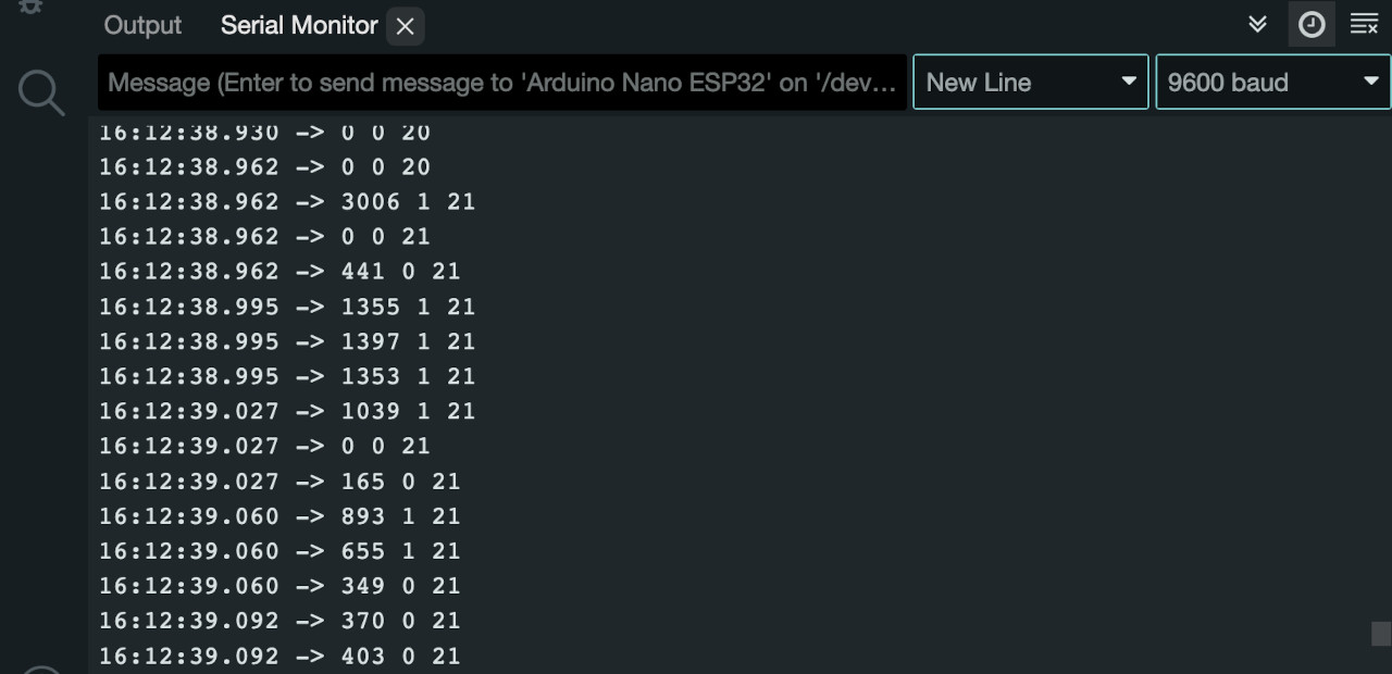
We can see that one knock makes the currentKnockValue variable transition from \(0\) to \(1\) a total of \(3\) times, but now our count only increments by \(1\), going from \(20\) to \(21\) with one actual knock.
We can see that in the serial monitor here:
The other way to debounce our signal is to use a low-pass filter. Instead of using the raw value of A0, we calculate a weighted sum of the current value with previous values. This makes the signal unable to change too fast, and effectively gets rid of the fast bounce fluctuations between \(0\) and \(1\).
One possible equation for a low-pass filter that essentially takes a weighted-sum average is:
int avgA0Value = 0.9 * prevA0Value + 0.1 * currentA0Value;
This is different from the averaging technique we saw in class where we kept an array with the last \(32\) values and used those to take the average of the signal.
This technique here is a little simpler to code because we don’t have to keep an array of \(32\) values. The average value here is composed of \(10\%\) of the current measured value and \(90\%\) of the previous value. And the previous value itself was \(10\%\) of a measured value and \(90\%\) of previous values, and so on and so on… The resulting effect of both techniques is very similar, but this one is easier to program.
If we look at some graphs, we can see that, while the peaks are smaller, they tend to look more well-defined, without much oscillation between high and low values:
We have to adjust the value of the THRESHOLD variable to be a little lower, but after that, we can use the following code to detect clean knock signals:
We can use the serial monitor again to check that we’re only counting one knock per knock action:
Cool. So we have a way to detect knocks and count them.
Let’s implement a simple knock detector that signals success if it detects \(10\) knocks in \(1500\) milliseconds, or \(1.5\) seconds.
Let’s add some lights to our circuit, to show successful or failed attempts at the knock pattern:
Drawing:
Schematic:
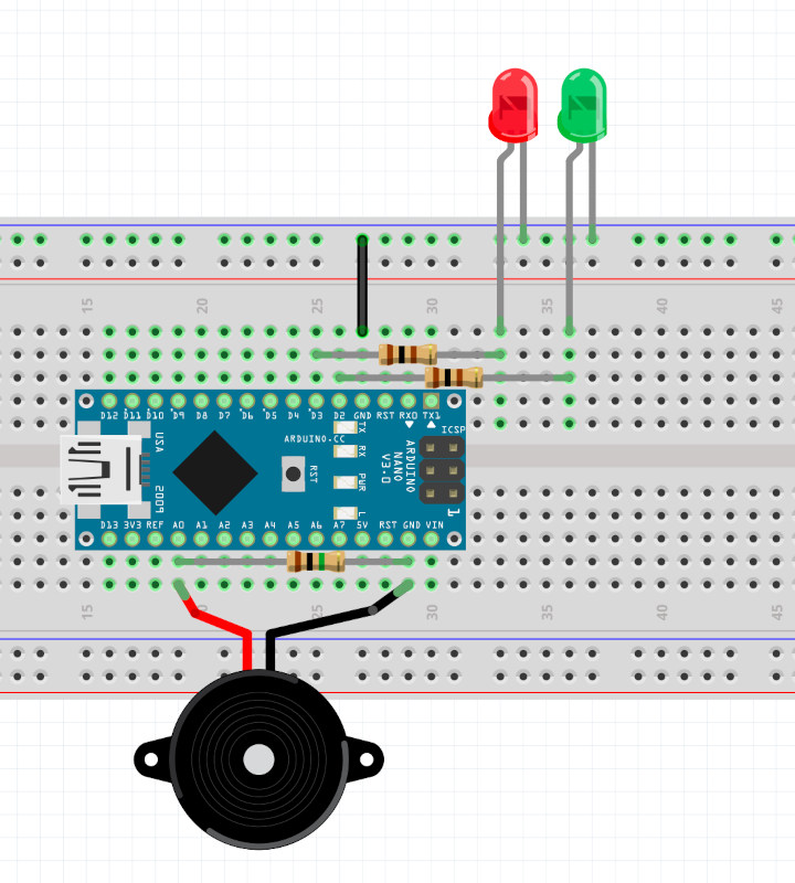
Board:
We can think of an FSM for this system that looks something like this:
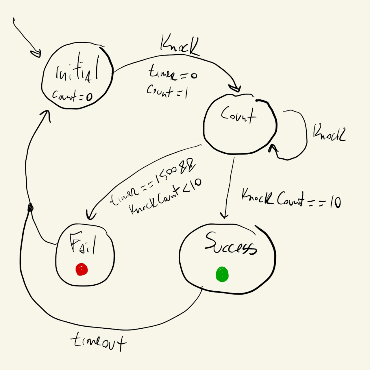
We have an initial state where we just wait for the first knock. The system stays here as long as there have been no knocks.
When the first knock is detected, we increment our knockCount variable, start our timer, and transition to the count state.
We stay in the count state for \(1500\) milliseconds counting knocks. If knockCount reaches \(10\) we transition to the success state, or, if the timer reaches \(1500\) milliseconds and knockCount is less than \(10\), we transition to the fail state.
We stay in the success or fail states for another \(1500\) milliseconds before resetting everything and moving back to the initial state.
The code for the FSM can be implemented like this:
We start by defining some time constants that we’ll need, enumerating our states, and initializing some counters and timers.
In loop(), the first thing we do is read the value at A0, debounce the signal, and store whether we have a valid knock on the knock variable.
Then, for each of the states we check for knocks, increment counters or restart timers as needed, and also set the LED values depending on which state we are in.
We can test our implementation now, by trying to knock \(10\) times within \(1500\) milliseconds:
The first number being printed is the currentState variable, and the second is knockCount.
It’s actually not very easy to knock \(10\) times in less than \(1.5\) seconds.
It’s quite challenging and stressful, actually, so let’s make this more fun, while still keeping our knock pattern/password secure.
Instead of signaling a successful sequence based on speed, maybe we can use something smarter and detect specific knock patterns.
The pattern we will detect is the Shave and a Haircut, but we will keep our code modular and extendable so it can easily be changed to different knock patterns.
This is the pattern:
We can start by thinking about what a Finite State Machine that detects specific patterns would look like. Similar to the FSM above, we have an initial state, where we just wait for the first knock, and then we have a “counting” state, except instead of just counting the knocks we also have to check if they happen in the right moments in time.
Our new FSM can look like this:
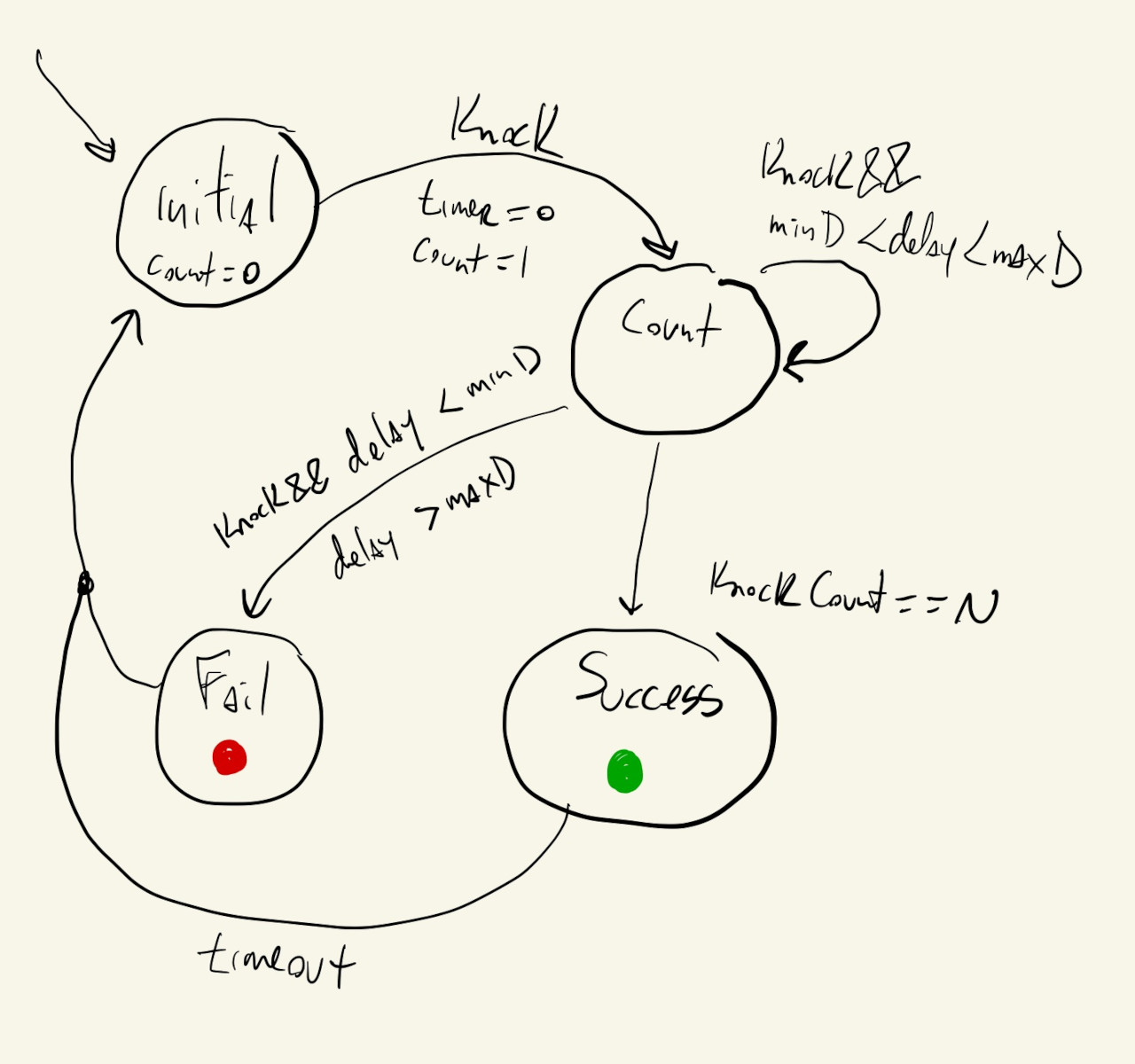
This is similar to the previous FSM, but now there are extra requirements about the timing of each knock.
Instead of requiring just a knock to stay in the count state and increment the counter, now that knock has to come after a specific number of milliseconds after the previous knock.
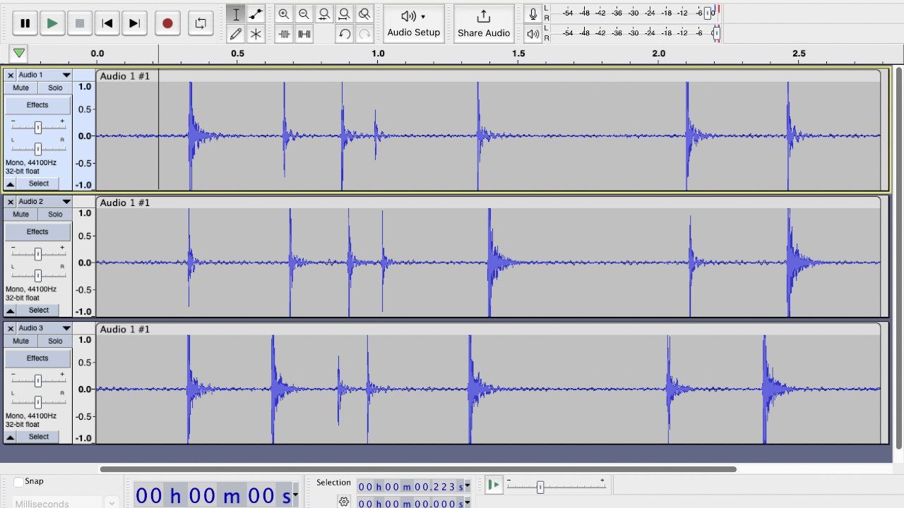
To figure out the times between each knock, we can clap the pattern out a couple of times on a microphone and measure some average distances between each peak of our wave form.
Something like this:
Now we just have to put this into our code.
We can use an array of expected knock delay, indexed by the number of correct knocks so far. For example, an array like this:
int DELAY[] = { 0, 300, 200, 130, 330, 700, 320 };
means that while our knockCount is \(0\), there is no expected delay. After the initial knock, when knockCount is \(1\), the next knock should happen with a delay of about \(300\) milliseconds. Once we have seen \(2\) knocks and knockCount is \(2\), the next knock should happen after \(200\) milliseconds, and so on.
And, while using the array above to detect exact knock delays would work, it’s really hard to repeat a knock pattern with the exact same delays between knocks, so we’ll allow the knocks to come within a \(100\) millisecond window of the values above, either \(50\) milliseconds too early or \(50\) too late.
While counting knocks, every time we detect a knock, this code will compute the delay between the last two knocks, and whether that delay falls within an acceptable range:
int knockDelay = millis() - prevKnockCountTime;
int knockDelayDifference = abs(knockDelay - DELAY[knockCount]);
prevKnockCountTime = millis();

if (knockDelayDifference < 50) {
  knockCount++;
} else {
  cState = FAIL_S;
}
If it does, we increment knockCount, otherwise it’s a wrongly timed knock and we’ll transition to the fail state.
Finally, we can change our code to implement this new logic:
And test by trying to tap out the pattern of the jiggle:
As before, the first number being printed is the currentState variable, and the second is knockCount.
Unfortunately, this video has no sounds and has to be re-recorded…